

Our production deliverables are derived from highly detailed, “as-built” 3D models that serve as the backbone of the manufacturing process. The foundation of this digital environment is the accurate surface model of the vessel that can either be developed entirely from scratch – using the lines plan and general construction drawings as references – or refined from an existing concept model, enhancing its fidelity to meet production standards.
Once the surface model is validated, it is transformed into a solid model, every surface is converted into a plate of defined thickness, corresponding precisely to the specifications outlined in the approved general construction drawings. This conversion process carefully accounts for material sheet sizes, structural requirements, bending and elongation limitations, and any project-specific constraints, ensuring the model is both manufacturable and faithful to the design intent.
")
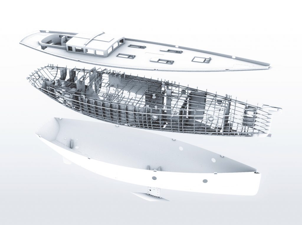
With the hull outer plating model complete, the next phase involves the comprehensive integration of all structural components, meticulously developed in accordance with the general construction plan and project’s specific requirements. It is at this stage that the vessel is fully engineered, translating the design into a constructible product.
The outcome is a fully detailed 3D model encompassing every individual part required for fabrication and assembly, whether CNC-milled components or standardized, pre-defined profiles. Each element is organized within a structured product hierarchy, with precise metadata assigned – defining material specifications, profile types, and other critical fabrication parameters. This digital assembly becomes the definitive source for production, ensuring clarity, traceability, and manufacturability at every step of the process.
The preparation of CNC files is carried out in two distinct stages, each critical to ensuring precision and efficiency in the manufacturing workflow. The first stage involves generating the part expansions – 2D unfolded projections of all relevant components. During this process, each surface is carefully evaluated to determine whether it requires bending or forming templates. Based on this analysis, the resulting flat patterns are enriched with essential fabrication data, including marking lines, bending allowances, and forming instructions, ensuring downstream processes are both accurate and repeatable.
In the second stage, nesting is performed – optimizing the layout of all expanded parts within the confines of the raw material stock. The objective is to maximize material usage while maintaining process efficiency. The output is a drawing file composed of AutoCAD entities, meticulously organized by operation specific layers, each one representing a distinct machining or task. This structured output streamlines CNC execution and aligns seamlessly with production protocols.
")
")
This is the stage where the digital model takes on its final form – translated into a complete, actionable set of workshop and assembly documentation. These deliverables guide the transformation of CNC-milled parts and standardized profiles into a coherent, buildable whole. They become the language through which design speaks to fabrication. The output is a comprehensive and highly coordinated package, including:
Transverse Construction Drawings
Longitudinal Construction Drawings
Bending and Forming Drawings
Assembly Drawings
Profile Reports
Profile Plots
Weight Calculation
Together, these documents form a unified construction manual, one that bridges the virtual model with the workshop floor, ensuring that every cut, weld and joint is made with purpose.