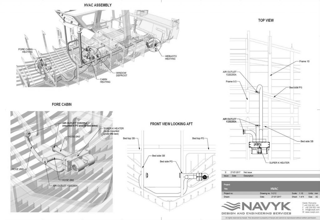

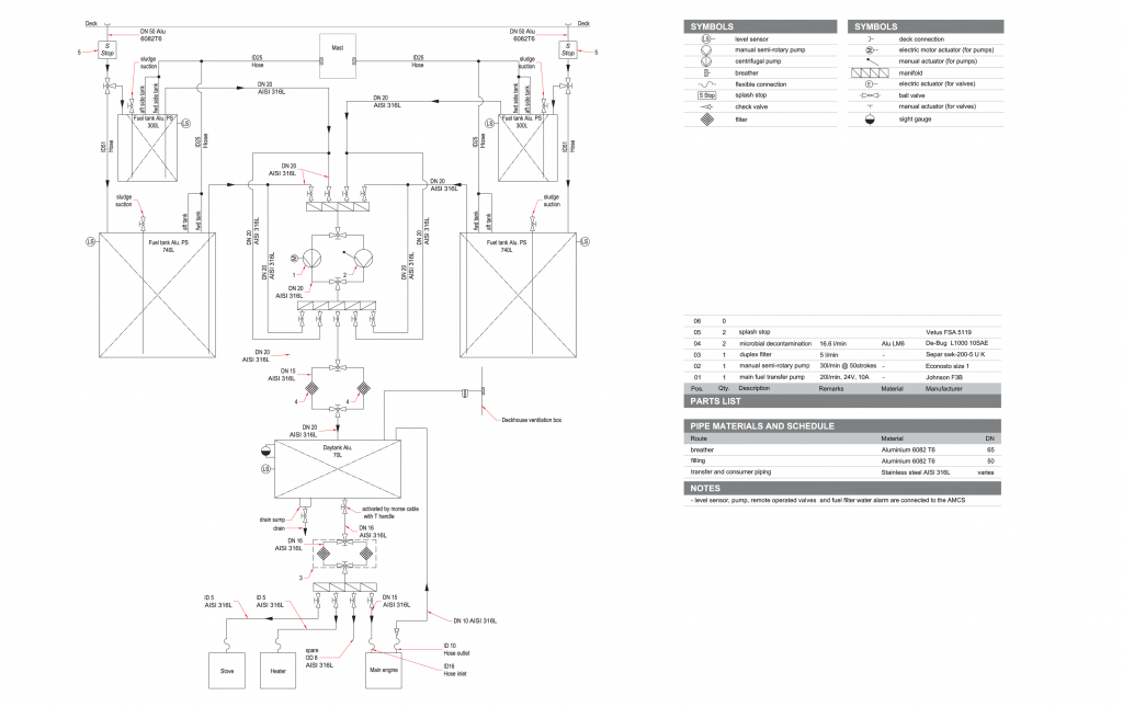
Based on the specifics of the project, we calculate key parameters and identify the necessary equipment that will form the foundation of a system. Each component, along with the interactions between them, is clearly represented in a comprehensive System Diagram. This diagram captures all essential aspects of the system’s design, ensuring clarity and cohesion. Additionally, the required equipment is listed within the diagrams, and its general arrangement is illustrated through a detailed layout drawing. Together, these two provide a clear and complete overview of the system’s structure and integration.
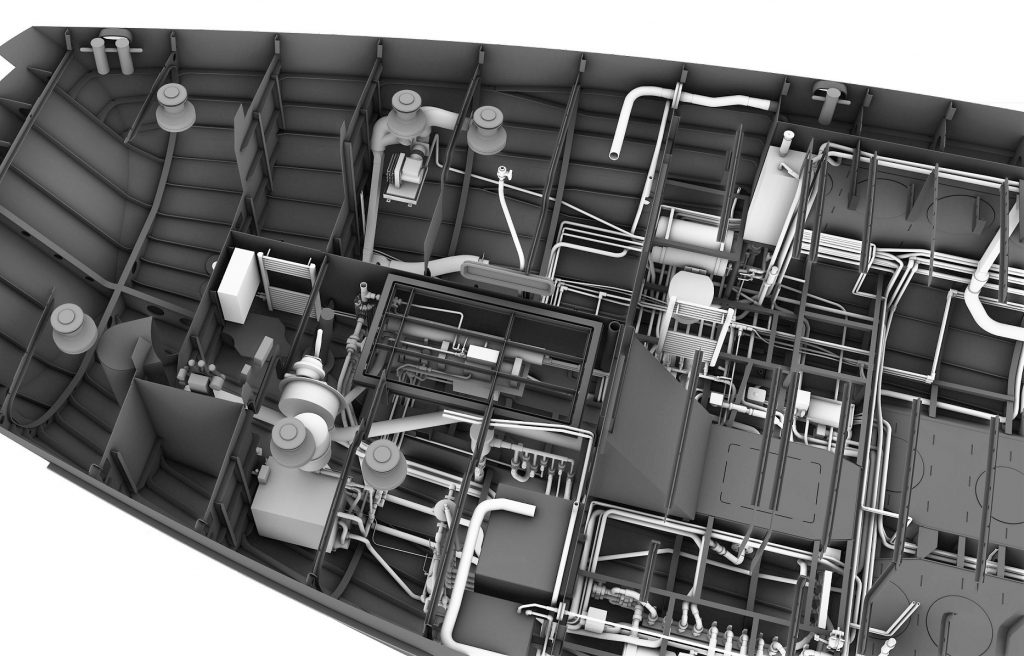
Starting from diagrams and the equipment layout plan, we carefully define and indicate the precise routes for all rigid and flexible pipes as they are integrated onboard the vessel. These pathways will be thoughtfully designed to ensure seamless installation, avoiding any interference with the ship’s structural framework or interior accommodations. All necessary connections and fittings will be incorporated with accuracy and attention to detail.
This entire process will be carried out within a comprehensive 3D environment, allowing for a clear, dynamic visualization of the system. Special consideration will be given to ensuring easy and safe access to all components, prioritizing serviceability and maintenance efficiency. In this way, we aim to deliver a system that is not only technically sound but also practical, sustainable, and built with the future in mind.
As we reach the final stage of the design process, the focus shifts to the creation of isometric drawings, a comprehensive visual representation of every pipe on board. This phase brings the entire system to life in detailed, three-dimensional clarity. At the heart of this stage are spool drawings and assembly drawings, each playing a vital role in transforming design into reality.
Spool drawings serve as precise blueprints for the pre-fabrication of modular piping sections. Each drawing captures the exact dimensions, components, and connections required, enabling fabricators to build with confidence and accuracy. Complementing them, assembly drawings offer a broader perspective, illustrating how each spool fits into the larger system. Together, they form a complete roadmap, from workshop to vessel.